Finally I managed to get my 20x4 Character LCD to work.
Someone in Arduino Forum mentioned that the most common problem in using LCD is connection related. This is proven true once again.
Just after getting the LCD I solder pin headers to the PCB and I thought the connection would no longer be a problem. However, after trying several hours using either Arduino Liquid Crystal Library or my hand-written code, I failed to make the LCD displaying anything. I started thinking it was the LCD's problem and trying to contact the seller from eBay to replace the module.
In the last try, when I was using multimeter to measure the voltage between GND and V0, surprisingly I found that when I put the probes on GND and V0, there's something displaying on the screen, although very dim.
It was very obvious the problem is the connectivity of V0. I had thought the soldering quality is pretty good, but seems it is not :-(. After re-solder that header , the "Hello World" finally displayed on the screen.
Now I will start writing my own LCD library. After all, the best way to understand how one thing works is to try it by yourself, right?
Friday, May 17, 2013
Monday, May 13, 2013
Arduino: Port Manipulation on Mega 2560
I am writing a library to output PAL/NTSC signals to a TV terminal, and I think it would be better to manipulate the port directly to gain faster access.
From http://www.arduino.cc/en/Reference/PortManipulation it was said PORTD can be used to control pin 0-7. However, sadly it does not work for me. digitalWrite and pinMode works well. But DDRD and PORTD has no response at all.
I start suspecting the document and trying other ports, and happily find PORTE works for pin 2-3. But not for the others. I think now it is time to test other ports and make a new mapping.
By testing, here's the ports corresponding to pin of Mega2560. It seems a little weird and I don't know why. If you have the same problem, I would suggest you to also try different PORT names on your board.
Hope this would help others that encounter the same problem.
| PIN number | PORT |
|---|---|
| 2 | PORTE (0x10) |
| 3 | PORTE (0x20) |
| 4 | PORTG (0x20) |
| 5 | PORTE (0x08) |
| 6 | PORTH (0x08) |
| 7 | PORTH (0x10) |
| 8 | PORTH (0x20) |
| 9 | PORTH (0x40) |
| 10 | PORTB (0x10) |
| 11 | PORTB (0x20) |
| 12 | PORTB (0x40) |
| 13 | PORTB (0x80) |
| 22-29 | PORTA (0x01-0x80) |
| 30-37 | PORTC (0x80-0x01) |
| 38-45 | PORTD (0x80-0x01) |
| 46-53 | <NOT_FOUND> |
Arduino: Using ATMega’s Internal Timer/Counter
Internal timer, aka hardware timers are associated with specific hardwares. This article will focus on talking about using hardware timers in Arduino boards using ATMega series processor.
What can a timer/counter do?
One of the most often usage of timer/counter is to trigger interrupts and execute routines in a given interval.
If you have a periodic task to be done using Arduino, one of the way is to use delay() to control the time in the loop iteration. However, as Arduino is a single-threaded environment, it is thus impossible to execute other codes during the delay period. The CPU time is thus wasted during the delay. Moreover, if there are multiple tasks with different intervals, you’ll have to adjust the interval very carefully to make them working together.
Using interrupt triggered by timer can avoid this kind of problem. By setting up a interrupt period and feeding to Arduino a interrupt service routine(ISR), the timer will trigger the routine automatically in the given interval.
Another usage of timer/counter is to generate PWM(Pulse-Width Modulation) signals. This is a way of simulating a continuous voltage area by varying the width of fixed-height pulses. In this article I will NOT talk too much about PWM as this functionality has been provided by Arduino system library and it’s rarely necessary for user to manually create PWM by their own. However, it is good to know that these functions are supported by the processor hardware.
Hardware Architecture
This section and the next one will look in depth of the hardware architecture of the timer module and how it works. It will contains a lot of technical detail help understanding the timer. If you are not interested in them, you can safely skip them and go directly to the “Example of Timer” section and go back to these when necessary.
ATMega640/1280/2560 series processors has 6 timers/counter. The datasheet can be found at: http://www.atmel.com/Images/doc2549.pdf and section 17 talks about timers. The following description text are from corresponding section of the datasheet.
Each timer is also a counter, which uses a register to store the cycles it counts. ATMega has two types of timers: 8-bit and 16-bit. The first one can count up to 0xFF = 255 cycles. The latter one can count up to 0xFFFF = 65535 cycles.
Timer 0 and timer 2 are 8-bit counters. Timer 0 is used by Arduino library to implements millis() and micros() call. Timer 2 is used to implement tone() call.
Timer 1, 3, 4, 5 are 16-bit counters. Timer 1 is used by Arduino Servo library, which is used to control servomotor. If you don’t use that library, it is okay to use this timer. Timer 3, 4, 5 are safe to use as no official library use them. I will focus more on 16-bit counters.
NOTICE
In the following description, hardware register name may be involved. As registers for different timers only differs by their numbers(for example, the counter register for timer 1 is TCNT1, and that for timer 2 is TCNT2), we will use lower case “n” to represents timer number in register name(like TCNTn for counter register).
|
The timer is comprised of three parts: counter unit, compare unit and input capture unit.
Counter Unit
The counting value is stored in register TCNTn.
Depending on the mode of operation used, the counter is cleared, incremented, or decremented
at each timer clock (clkTn). The clkTn can be generated from an external or internal clock source, selected by the Clock Select bits (CSn2:0).
When no clock source is selected (CSn2:0 = 0) the timer is stopped. However, the TCNTn value can be accessed by the CPU, independent of whether clkTn is present or not. A CPU write overrides (has priority over) all counter clear or count operations.
The counting sequence is determined by the setting of the Waveform Generation mode bits (WGMn3:0) located in the Timer/Counter Control Registers A and B (TCCRnA and TCCRnB).
The Timer/Counter Overflow Flag (TOVn) is set according to the mode of operation selected by the WGMn3:0 bits. TOVn can be used for generating a CPU interrupt.
Compare Unit
During the counting, the 16-bit comparator continuously compares TCNTn with the Output Compare Register (OCRnx). If TCNT equals OCRnx the comparator signals a match. A match will set the Output Compare Flag (OCFnx) at the next timer clock cycle.
If interrupts is enabled (OCIEnx = 1), the Output Compare Flag generates an Output Compare interrupt. The OCFnx Flag is automatically cleared when the interrupt is executed.
Input Capture Unit
This unit is only provided in 16-bit counters. Thus timer 0 and timer 2 cannot use this function.
The Timer/Counter incorporates an input capture unit that can capture external events and give them a timestamp indicating time of occurrence. The external signal indicating an event, or multiple events, can be applied via the ICPn pin or alternatively, for the Timer/Counter1 only, via the Analog Comparator unit. The timestamps can then be used to calculate frequency, duty-cycle, and other features of the signal applied. Alternatively the time-stamps can be used for creating a log of the events.
When an event occurs on the Input Capture Pin (ICPn), a capture will be triggered, and the 16-bit value of the counter (TCNTn) is written to the Input Capture Register (ICRn). The Input Capture Flag (ICFn) is set at the same system clock as the TCNTn value is copied into ICRn Register.
If interrupt is enabled (TICIEn =1), the input capture flag generates an input capture interrupt. The ICFn flag is automatically cleared when the interrupt is executed. Alternatively the ICFn flag can be cleared by software by writing a logical one to its I/O bit location.
How to use the timer
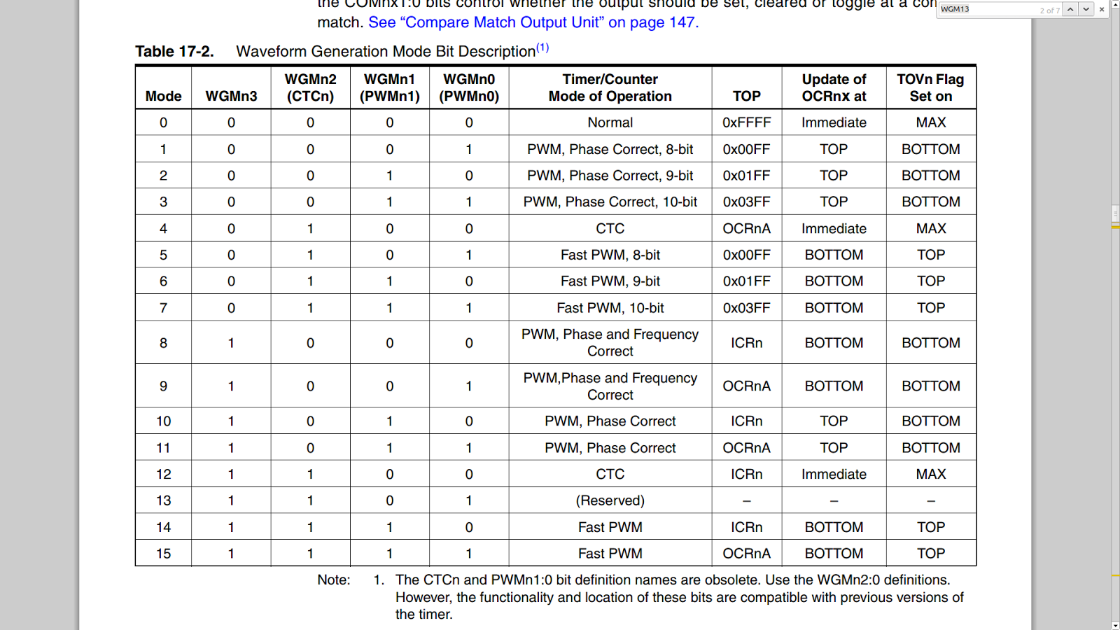
We will start by viewing the possible working mode of the timers. The following table describing available modes, in which 0, 4, 12 are the only non-PWM mode and are what will be used by us.
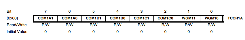
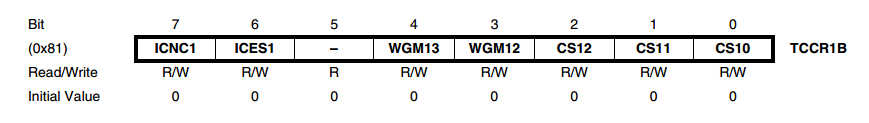
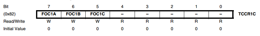
The register TCCRnA and TCCRnB are used to select the mode. Here’re the definition of each bits of these 2 registers. We take TCCR1A/B as an example as TCCRnA/B all work in the same way.
Before talking about the modes, I want to first introduce the concept of prescaler, which will later be used frequently.
Prescaler
How long will it take for a 16-bit counter to generate an overflow, which is by default the longest time between signals?
Here we assume all the timers work in internal clock, which has a frequency of 16MHz. Thus each cycle will take 1/16 us and the time required by the counter to generate an overflow interrupt is 65536/16 = 4096 us, which is only 4 ms. This is too short for most of the periodic tasks.
Prescaler is designed to solve this problem. In prescaler mode, the counter will be operated only when a given number N, of hardware cycles passed. This means the frequency is decreased by N times.
For example, when the prescaler is set to be 2, it takes 2 cycles for the counter to increase by 1. Thus the timer frequency decreased to 8MHz and overflow interval will be 65536/8 = 8192 us.
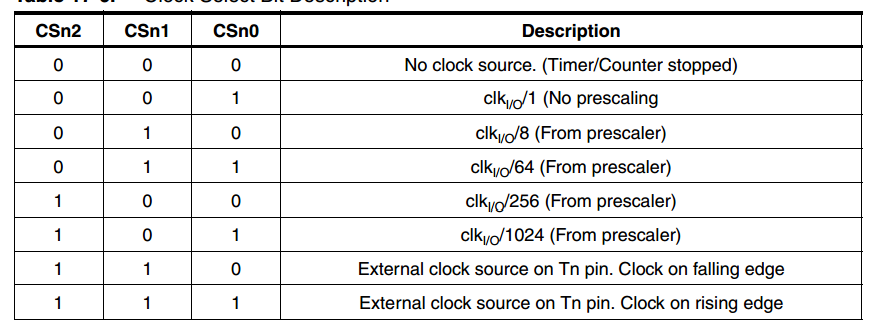
The prescaler value is controlled by the CSn2:0 bits in TCCRnB. The following table describes how they works. From the table we know that the maximal prescaler value is 1024, which means it takes 64 us for the counter to increase 1, and it takes around 4.2 s for the counter to generate an overflow interrupt. This would be enough for most tasks. If you requires a longer delay, a software counter should be used in the program to control it.
We will start by looking into the first mode, namely normal mode, in which all the WGMn bits are zero.
Normal Mode
The simplest mode of operation is the Normal mode (WGMn3:0 = 0). In this mode the counting direction is always up (incrementing), and no counter clear is performed. The counter simply overruns when it passes its maximum 16-bit value (MAX = 0xFFFF) and then restarts from the BOTTOM (0x0000). In normal operation the Timer/Counter Overflow Flag (TOVn) will be set in the same timer clock cycle as the TCNTn becomes zero. The TOVn Flag in this case behaves like a 17th bit, except that it is only set, not cleared. However, combined with the timer overflow interrupt that automatically clears the TOVn Flag, the timer resolution can be increased by software. There are no special cases to consider in the Normal mode, a new counter value can be written anytime.
The Input Capture unit is easy to use in Normal mode. However, observe that the maximum interval between the external events must not exceed the resolution of the counter. If the interval between events are too long, the timer overflow interrupt or the prescaler must be used to extend the resolution for the capture unit. The Output Compare units can be used to generate interrupts at some given time. Using the Output Compare to generate waveforms in Normal mode is not recommended, since this will occupy too much of the CPU time.
CTC Mode
In Clear Timer on Compare or CTC mode (WGMn3:0 = 4 or 12), the OCRnA or ICRn Register are used to manipulate the counter resolution. In CTC mode the counter is cleared to zero when the counter value (TCNTn) matches either the OCRnA (WGMn3:0 = 4) or the ICRn (WGMn3:0 = 12). The OCRnA or ICRn define the top value for the counter, hence also its resolution. This mode allows greater control of the compare match output frequency. It also simplifies the operation of counting external events.
An interrupt can be generated at each time the counter value reaches the TOP value by either using the OCFnA or ICFn Flag according to the register used to define the TOP value. If the interrupt is enabled, the interrupt handler routine can be used for updating the TOP value. However, changing the TOP to a value close to BOTTOM when the counter is running with none or a low prescaler value must be done with care since the CTC mode does not have the double buffering feature. If the new value written to OCRnA or ICRn is lower than the current value of TCNTn, the counter will miss the compare match. The counter will then have to count to its maximum value (0xFFFF) and wrap around starting at 0x0000 before the compare match can occur. In many cases this feature is not desirable.
For generating a waveform output in CTC mode, the OCnA output can be set to toggle its logical
level on each compare match by setting the Compare Output mode bits to toggle mode
(COMnA1:0 = 1). The OCnA value will not be visible on the port pin unless the data direction for
the pin is set to output (DDR_OCnA = 1). The waveform generated will have a maximum frequency of fOCnA = fclk_I/O/2 when OCRnA is set to zero (0x0000).
The waveform frequency is defined by the following equation:
fOCnA=fclkIO/(2N(1+OCRnA))
The N variable represents the prescaler factor (1, 8, 64, 256, or 1024).
As for the Normal mode of operation, the TOVn Flag is set in the same timer clock cycle that the counter counts from MAX to 0x0000.
It should also be noticed that there are three channels A, B, C available for generating Compare Match Interrupt, but only OCRnA is used to clear the timer. Thus if OCRnB and OCRnC is set a value that is larger than OCRnA, there will be a high possibility that these interrupts not be triggered as the counter never reach their value.
Enabling Interrupts
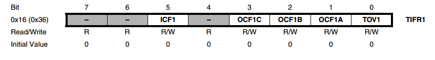
Interrupts can be enabled or disabled by setting the corresponding bits of TIMSKn register. There are 5 types of interrupt available

ICIEn: Timer/Counter n, Input Capture Interrupt Enable
When this bit is written to one, the Timer/Counter n Input Capture interrupt is enabled. The corresponding Interrupt Vector TIMERn_CAPT_vect is executed when the ICFn Flag, located in TIFRn, is set.
OCIEnC: Timer/Counter n, Output Compare C Match Interrupt Enable
When this bit is written to one, the Timer/Counter n Output Compare C Match interrupt is enabled. The corresponding Interrupt Vector TIMERn_COMPC_vect is executed when the OCFnC Flag, located in TIFRn, is set.
OCIEnB: Timer/Counter n, Output Compare B Match Interrupt Enable
When this bit is written to one, the Timer/Counter n Output Compare B Match interrupt is enabled. The corresponding Interrupt Vector TIMERn_COMPB_vect is executed when the OCFnB Flag, located in TIFRn, is set.
OCIEnA: Timer/Counter n, Output Compare A Match Interrupt Enable
When this bit is written to one, the Timer/Counter n Output Compare A Match interrupt is enabled. The corresponding Interrupt Vector TIMERn_COMPA_vect is executed when the OCFnA Flag, located in TIFRn, is set.
TOIEn: Timer/Countern, Overflow Interrupt Enable
When this bit is written to one, the Timer/Countern Overflow interrupt is enabled. The corresponding Interrupt Vector TIMERn_OVF_vect is executed when the TOVn Flag, located in TIFRn, is set.
How to calculate required frequency
In this section I want to talk about some guideline about efficiently get a required frequency. This will apply only when you are using the internal clock of ATMega.
The easiest way to use the timer is to let it works in normal mode and make use of the Overflow Interrupt. As described above, there are 5 prescaler values: 1, 8, 64, 256, 1024. When working in normal mode, these values corresponding to the frequency of 16MHz, 2MHz, 250KHz, 62.5KHz and 15.625KHz. Thus the final output frequency is 244.1 Hz, 30.5 Hz, 3.8 Hz, 0.95Hz and 0.24Hz. Use the one that is most close to your request.
CTC mode provides more choice for frequency selection. By adjusting the OCRnx register, the frequency generated by CTC varies between the maximal and minimal values. CTC mode could be used generate the following frequencies of strobe signals.
Prescaler Value
|
Maximal Frequency
|
Minimal Frequency
|
1
|
16MHz
|
244Hz
|
8
|
2MHz
|
30.5Hz
|
64
|
250KHz
|
3.8Hz
|
256
|
62.5KHz
|
0.95Hz
|
1024
|
15.625KHz
|
0.24Hz
|
Example code
Example 1 : Using normal mode, Overflow Interrupt
This example use Timer 1 to toggle LED on pin 13 with an almost 4 seconds interval.
#define ledPin 13
void setup()
{
pinMode(ledPin, OUTPUT);
// initialize timer1
cli(); // disable all interrupts
TCCR1A = 0; // Clean the registers
TCCR1B = 0;
TCCR1B |= (1 << CS12) | (1 << CS10); // Prescaler 1024
TIMSK1 |= (1 << TOIE1); // enable timer overflow interrupt
sei(); // enable all interrupts
}
ISR(TIMER1_OVF_vect) // interrupt service routine
{
digitalWrite(ledPin, digitalRead(ledPin) ^ 1);
}
void loop()
{
}
|
Example 2 : Normal mode, use Output Compare Match Interrupt
In this example I use 2 Leds, one will be toggled when the counter is 32767, another will be toggled when the counter overflows. This is implemented using output compare match interrupt.
#define ledPin 13
#define ledPin2 31
void setup()
{
// initialize timer1
cli(); // disable all interrupts
TCCR3A = 0;
TCCR3B = 0;
OCR3A = 32767;
TCCR3B |= (1 << CS32); // Prescaler 256
TIMSK3 |= (1 << TOIE3); // enable compare A Match Interrupt
TIMSK3 |= (1 << OCIE3A); // enable compare B Match Interrupt
sei(); // enable all interrupts
pinMode(ledPin, OUTPUT);
pinMode(ledPin2, OUTPUT);
}
ISR(TIMER3_OVF_vect) // interrupt service routine
{
digitalWrite(ledPin, !digitalRead(ledPin));
}
ISR(TIMER3_COMPA_vect) // interrupt service routine
{
digitalWrite(ledPin2, digitalRead(ledPin2)^1);
}
void loop()
{
}
|
Example 3 : Using CTC mode, Output Compare Match Interrupt
This example demonstrate how to use OCR3A register to trigger an interrupt on Compare Match.
In the example, the prescaler was set to be 1024, which means an full overflow cycle will cost around 4s. The OCR3A is set to be 16383, which is 1/4 of the full cycle. It will take around 1s to trigger the compare and match interrupt.
Note here we set OCR3A to be 16383 rather than 16384. This is because the processor need a cycle to clear the TCNTn register and trigger the interrupt.
#define ledPin 13
void setup()
{
pinMode(ledPin, OUTPUT);
// initialize timer1
cli(); // disable all interrupts
TCCR3A = 0; // Clean the registers
TCCR3B = 0;
TCCR3B |= (1 << WGM12); // Mode 4, CTC
OCR3A = 16383; // 1/4 of counter
TCCR3B |= (1 << CS32) | (1 << CS30); // Prescaler 1024
TIMSK3 |= (1 << OCIE3A); // enable compare A Match Interrupt
sei(); // enable all interrupts
}
ISR(TIMER3_COMPA_vect) // interrupt service routine
{
digitalWrite(ledPin, digitalRead(ledPin) ^ 1);
}
void loop()
{
}
|
Complete Reference of all Timer Registers
Subscribe to:
Posts (Atom)